HuBMAP CODEX Data
Last Updated: 6/1/2020
Overview
This document details CODEX data states, metadata fields, file structure, QA/QC thresholds, and data processing.
Description
CODEX is a strategy for generating highly multiplexed images of fluorescently-labeled antigens. In brief, antibodies to antigens of interest are labeled with antigen-specific oligonucleotide barcodes. The barcoded antibodies are then applied to a tissue sample where they bind to target antigens. Complementary oligonucleotide probes tagged with fluorophores are then applied to the tissue sample, one antigen-specific probe at a time, allowing hybridization to the barcodes on the target antibodies. An image is captured, the probes are washed off and the process is repeated. Up to 50 protein targets are interrogated, one imaging cycle at a time, allowing generation of a composite image of up to 50 protein targets within a single tissue section.
Definitions
There are a variety of terms used in this document that may not be familiar to all HubMap users. The following figures illustrate several of these terms:
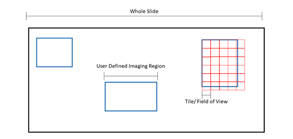
Figure 1: Pictorial representation of microscopy terms. The black box is an example slide or cover slip where the sample is located. Blue boxes are examples of “regions” or user defined imaging areas. For instance, if you want to image a specific structure in the tissue, you would designate a “region” over the structure. Red boxes are examples of “tiles” or the microscope “field of view”. The size of the tile is dependent on the microscope set up and objective. Tiles will fill the region. Because the field of view cannot be changed, tiles will overhang from the region, ensuring the entire region is imaged at the expense of extra tiles being acquired.
 Figure 2: Images are generally acquired with adjacent tiles overlapping, as indicated by the dark regions in the image on the right above. Overlap enhances alignment of tiles for stitching to create a composite image, as shown in Figure 4 below.
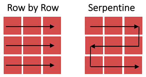 Figure 3: Images of tiles are captured as the stage moves across the imaged region row by row (left) or via a serpentine (or snake-like) path (right).
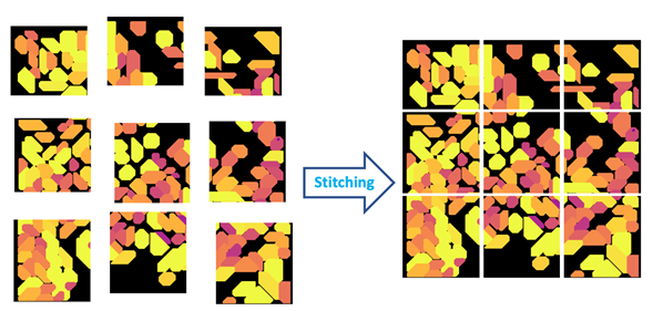 Figure 4: Stitching is the process of aligning and merging neighboring image tiles into a single composite image.
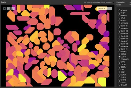 Figure 5: Segmentation of a microscopy image is performed by an algorithm that predicts edges of structures. Structures may be nuclear membrane, cell membranes or larger structures such as tubules.
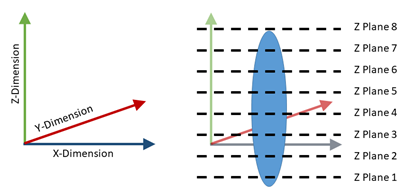 Figure 6: Example defined plane (left) with example imaged z planes (right).
HuBMAP CODEX Data States (Levels)
| Data State | Description | Example File Type |
|---|---|---|
| 0 | Raw image data: This is the data that comes directly off the microscope without preprocessing; sometimes referred to as tiled or unstitched data. (may not always be included). | CZI, TIFF |
| 1 | Processed Microscopy data: Can include stitching, thresholding, background subtraction, z-stack alignment, deconvolution | CZI, TIFF, OME-TIFF |
| 2 | Segmentation: Computationally predicted cell (nucleus, cytoplasm) and/or structural boundaries (tubules, ventricles, etc.) | CSV, TIFF |
| 3 | Annotation (Cells and Structures): Interpretation of microscopy image and/or segmentation in terms of biology (e.g. unhealthy vs healthy, cell-type, function, functional region). | TIFF, PNG |
HuBMAP Metadata
All HuBMAP CODEX data will have searchable metadata fields. This metadata field schema now resides in Github where it can be viewed and downloaded. Any further changes must now be implemented by filing a Github issue for Chuck McCallum.
Associated JSON Files
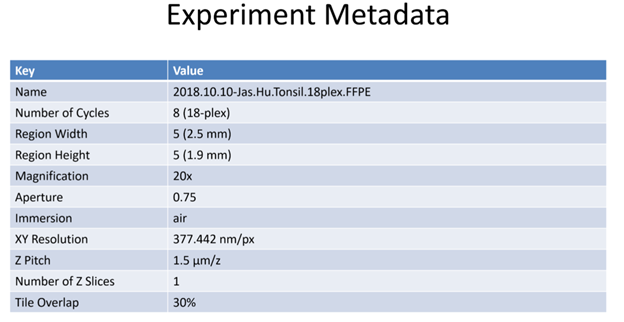
In addition, all HuBMAP CODEX data will have an associated json file which may contain the following additional metadata fields:
| Field | Definition | Example | |
|---|---|---|---|
| “version” | Software version used | standalone-1.6.0.16 | |
| “name” | Descriptive name assigned to the data | drv_CX_19-004_LN_R1 | |
| “dateProcessed” | Date of experiment | 2020-01-06T10:38:03.257-05:00 [America/New_York] | |
| “path” | Local file path in experimenter’s lab indicating where the raw (state 0) data produced was saved by the instrument. Generally not important. | “G:\SHARE\HuBMAP\Codex_dataset\src_CX_19-004_LN_R1 | |
| “outputPath” | Local file path in experimenter’s lab indicating where the processed (state > 0) data was saved. Generally this field is not important. | G:\SHARE\HuBMAP\Codex_dataset\drv_CX_19-004_LN_R1 | |
| “objectiveType” | Brand/specification of the microscope objective lens being used | air | |
| “magnification” | Microscope objective lens magnification (e.g. 20x) | 20 | |
| “aperture” | Numerical aperture of the lens | 0.75 | |
| “xyResolution” | Spatial resolution (minimum distance that can be resolved by the microscope), typically in nanometers. | 377.4463383838384 | |
| “zPitch” | Distance between Z planes (typically µm) | 1500.0 | |
| “wavelengths” | Excitation wavelength in nanometers (energy of light used for given channel). One value per channel. | [ 358, 488, 550, 650 ] | |
| “bitness” | Bit depth of each channel | 16 | |
| “numRegions” | How many separate regions are being imaged | 1 | |
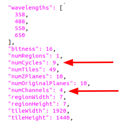
| “numCycles” | How many fluorescent stain-strip cycles are included in the run | 9 | |
| “numTiles” | Number x direction tiles times number of y direction tiles (area in number of tiles to be collected) | 25 | |
| “numZPlanes” | Number x direction tiles times number of y direction tiles (area in number of tiles to be collected) | 20 | |
| “numOriginalPlanes” | How many user-defined z-planes were entered in the Akoya software. Generally the same as numZPlanes. | 20 | |
| “numChannels” | Number of fluorescent channels imaged during each cycle. | 4 | |
| “regionWidth” | Number of horizontal tiles across the region collected | 5 | |
| “regionHeight” | Number of vertical tiles across region collected | 5 | |
| “tileWidth” | Tile horizontal size (field of view) | 1920 | |
| “tileHeight” | Tile vertical size (field of view) | 1440 | |
| “tileOverlapX” | Percent of overlap between tiles in x dimension. (e.g., 30% overlap) | 0.3 | |
| “tileOverlapY” | Percent of overlap between tiles in y dimension. (e.g., 30% overlap) | 0.3 | |
| “tilingMode” | Pattern of stage movement of microscope while acquiring tiles. | snakeRows | |
| “backgroundSubtractionMode” | Method used to subtract the background fluorescence from stained images | auto | |
| “driftCompReferenceCycle” | Cycle used for drift correction in imaging. Some datasets show this as “referenceCycle” | 2 | |
| “driftCompReferenceChannel” | Channel used for drift correction in imaging. Some datasets show this as “referenceChannel”. | 1 | |
| “bestFocusReferenceCycle” | Cycle used for z-focus selection in imaging | 2 | |
| “bestFocusReferenceChannel” | Channel used for z-focus selection in imagingIntensity | Detector Counts | 1 |
| “numSubTiles” | Number of tiles within a tile (generally one for HuBMAP data) | 1 | |
| “focusingOffset” | User defined linear offset of the computationally determined focus z-plane. | 0 | |
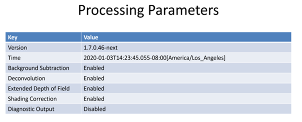
| “useBackgroundSubtraction” | Was computational background subtraction processing used | true | |
| “useDeconvolution” | Was computational deconvolution processing used | true | |
| “useExtendedDepthOfField” | Was extended depth of field used | true | |
| “useShadingCorrection” | Was shading correction used | true | |
| “use3dDriftCompensation” | Was 3D (z-plane) drift compensation used | true | |
| “useBleachMinimizingCrop” | Was bleach minimizing crop used | false | |
| “useBlindDeconvolution” | Was blind deconvolution used | false | |
| “useDiagnosticMode” | Was diagnostic mode used | true | |
| “multipointMode” | Was multipoint microscope focus mode used | false | |
| “HandEstain” | Was H and E stain mode used | false | |
| “channelNames” | The microscope-defined names of the fluorophore | channelNamesArray[ ] | |
| “channelNamesArray” | List of stains, See right. | [ “DAPI-01”,”Blank”, “Blank”, “Blank”, “DAPI-02”, “CD31”, “CD8”, “CD45”, “DAPI-03”, “CD20”,”Ki67”, “CD3e” ] | |
| “exposureTimes” | Length of time (usually in milliseconds) the tile is exposed to excitation light. | exposureTimesArray [ ] | |
| “numerical_aperture” | The objective numerical aperture | 0.75 | |
| “z_pitch” | Spacing between each z-plane in microns | 0.0 | |
| “region_names” | List: user-defined names of regions | [ “reg1” ] | |
| “regldx” | List: numerical index of the region | [ 1 ] | |
| “cycle_lower_limit” | Lowest cycle recorded | 1 | |
| “cycle_upper_limit” | Highest cycle recorded | 9 | |
| “region_width” | Number of tiles in the X-dimension | 5 | |
| “region_height” | Number of tiles in the Y-dimension | 5 | |
| “num_z_planes” | Number of Z-planes | 20 | |
| “tile_width” | Number of pixels in the X-dimension | 1344 | |
| “tile_height” | Number of pixels in the Y-dimension | 1007 | |
| “tile_overlap_X” | Pixel overlap in the X direction | 576 | |
| “tile_overlap_Y” | Pixel overlap in the Y direction | 432 | |
| antibody_metadata | Pointer to a table of antibody target proteins, names, IDs, with the corresponding cycles and channels. | Such as: Ab1targetProtein, Ab1_name,ID#,cycle_#,channel_#; Ab2targetProtein, Ab2_name,ID#,cycle_#,channel_#; Ab3name,ID#,cycle_#,channel_# |
Antibody Metadata
Each TMC will provide a file listing each antibody name, respective cycle and channel. This metadata file will then inform later processes at the HIVE and be used for labeling. Further, we aim to curate the final antibody list with expert interpretation of redundant names to make antibodies and markers a searchable criteria within the HuBMAP database.
HuBMAP CODEX Raw File Structure
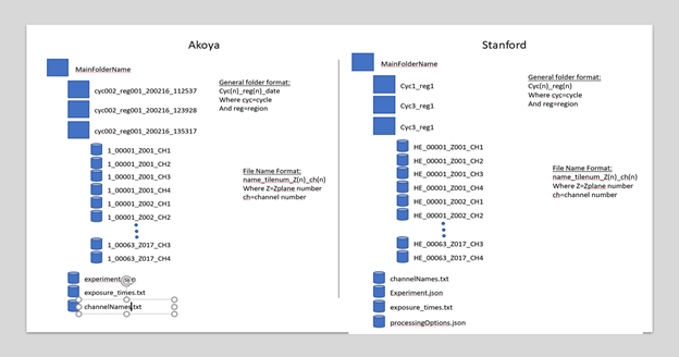
- The general structure of the level 0 (raw) data produced by the Akoya software (HuBMAP data generated by UF & Vanderbilt) and Stanford software is shown in the image below. Stanford employs a modified pipeline. If the HandEstain field in Stanford’s Experiment.json CODEX data is true, then additional folders are generated for the HandE cycle named as “HandE_reg1”. These are treated as separate cycles.
Other differences between CODEX software employed by Stanford versus Akoya proprietary software are documented here.
- Segmentation files in the processed data contributed by the TMC’s can be found in the following locations:
Stanford cell segmentation results can be found in the location mentioned below. You can see several text files generated per tile named as tilename-compensated.txt and tilename-uncompensated.txt. In addition to that, FCS and CSV files are stored based on the tiles, which are mainly used for analysis. The masks per tile can be found as .pngs which contain the images of cell boundaries.
The exact same data from Stanford is also available in an image sequence format, which stores the data in the same folder structure as Akoya’s format. But we can ignore this processed dataset with image sequence for analysis purposes.
| Type of Segmentation/Description | Descriptor (the name should contain the following) | Location |
|---|---|---|
| Stanford - cell segmentation | *_processed | https://app.globus.org/file-manager?origin_id=28bbb03c-a87d-4dd7-a661-7ea2fb6ea631&origin_path=%2FStanford%20TMC%2F26191c2719339be0c3fa6dc8a7ba3550%2F20190514_HUBMAP_CL1_processed%2F |
| Stanford - cell segmentation | *_processed-ImgSeq | https://app.globus.org/file-manager?origin_id=28bbb03c-a87d-4dd7-a661-7ea2fb6ea631&origin_path=%2FStanford%20TMC%2F26191c2719339be0c3fa6dc8a7ba3550%2F20190514_HUBMAP_CL1_processed-ImgSeq%2F |
| University of Florida | drv_* | https://app.globus.org/file-manager?origin_id=28bbb03c-a87d-4dd7-a661-7ea2fb6ea631&origin_path=%2FUniversity%20of%20Florida%20TMC%2F03043e079260d180099579045f16cd53%2F |
HuBMAP QA/QC of raw (state0) data files
- Files submitted by the TMC’s will be validated by the TMC in the following steps: A) Checked for zero length files B) The number of (raw) folders should be equal to the number of cycles * number of regions of interest C) The number of image files (TIFF) should be equal to the number of z planes(Z) * number of tiles(X) * number of tiles(Y) * number of channels.
If files fail to meet this validation criteria, they will not be submitted to the HIVE.
- A cycle for assessing background (“blanks”) should be included in every CODEX experiment. At a minimum, the first cycle should be filled with “blanks” with an additional “blank” cycle for each change in exposure time. [identified in the channel_names file which will be labeled as “Blank”].
If no blanks have been included within the CODEX dataset, the recommended action by the HIVE is to reject the dataset.
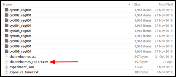
3) After acquisition of the dataset, the CODEX commercial instrument generates a “.txt” “channelnames” file which lists the marker per channel/per cycle and has the general structure shown below. The operator saves a copy as a “.csv” file named channelnames_report and annotates each channel/cycle as described below. As shown in this example, DAPI is a DNA-binding fluorescent dye that serves as a control detected in channel 1 for each hybridization cycle (DAPI-01, DAPI-02, etc):
DAPI-01
Blank
Blank
Blank
DAPI-02
CD31
CD8
Empty
DAPI-03
CD20
Ki67
CD3e
DAPI-04
SMActin
Podoplanin
CD68
DAPI-05
PanCK
Empty
Blank
etc......
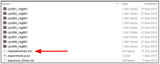
How to read channelnames
Blank channel is used to monitor autofluorescence at each channel (wavelength) which typically increases over time and with each cycle.
Empty channel indicates a channel (wavelength) that was not used to detect any marker during a specific cycle.
For each dataset, the number of cycles and channels is reported in the experiment.json file:
How to read channelnames_report
The operator annotates each cycle/channel with TRUE/FALSE to indicate whether or not the expected signal or absence of signal was detected, i.e. antibody bound to the target protein or the channel was Blank or Empty.
DAPI-01, TRUE
Blank, TRUE
Blank, TRUE
Blank, TRUE
DAPI-02, TRUE
CD31, FALSE
CD8, FALSE
Empty, FALSE
DAPI-03, TRUE
CD20, FALSE
Ki67, FALSE
CD3e, FALSE
DAPI-04, TRUE
SMActin, FALSE
Podoplanin, FALSE
CD68, FALSE
DAPI-05, TRUE
PanCK, FALSE
Empty, TRUE
Blank, TRUE
etc......
How to evaluate the channels to create the QA/QC channelnames_report.cvs file
Using commercial version:
- Process the data using the processing tool provided by Akoya.
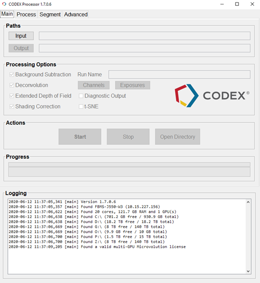
- Generate the Report ppt file by enabling the option at the prompt.

The Akoya integrated processing step (go to CODEX help for further information) produces an Image Analysis Report for each region acquired. The report includes the following documentation:
A histogram and sample image is generated for every acquired channel. Each row is a cycle, containing its corresponding channels. Top-left image and histogram is always the first cycle, first channel. Image and histogram to their right is the same cycle, second channel.
The displayed image is a full-resolution cropped image that has the greatest standard deviation among those sampled. Each image may be of different location within the region, depending on the expression pattern. For example, cropped images for DAPI cycles 2 and 3 below differ in their sampling location.
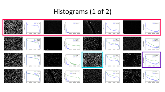
(Magenta) A single cycle. (Cyan) Full-resolution cropped image. (Purple) Histogram.
The histogram displays pixel frequency of signal intensities found within the region image. The horizontal intensity axis covers the 16-bit range (0 ~ 65535), while the vertical frequency axis auto-scales to the number of pixels found. Frequency is in logarithmic scale to better represent lower frequencies that correspond to biomarker signal.
Additionally, all cycles except the first contains two histogram plots. All purple plots are of the first cycle, which can be a reference for comparison, especially if the first cycle contains blank cycles. The legend specifies which biomarker the histogram represents.
A summary section contains basic statistics of biomarker region images. Each slide contains four cycles and their corresponding channels. Any non-biomarker channel (i.e. containing “DAPI,” “blank” or “empty”) will be grayed out.
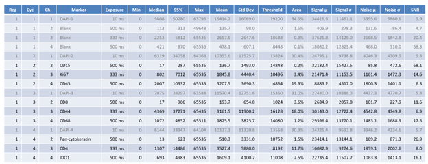
There are 18 columns for each channel. All pixel intensities are in 16-bit ranges (0 ~ 65535).
| Name | Details |
|---|---|
| Reg | Region number |
| Cyc | Cycle number |
| Ch | Channel number |
| Marker | Marker name |
| Exposure | Exposure time in milliseconds |
| Min | Minimum pixel intensity of the region image |
| Median | Median pixel intensity |
| 95% | 95-percentile pixel intensity |
| Max | Max pixel intensity |
| Mean | Mean pixel intensity |
| Std Dev | Standard deviation |
| Threshold | Binarization threshold found by Otsu’s method |
| Area | Area of the region image above the threshold (i.e. signal area) |
| Signal µ | Mean pixel intensity of the area above the threshold (i.e. signal area |
| Signal σ | Standard deviation of the signal area |
| Noise µ | Mean pixel intensity of the area below the threshold (i.e. background area) |
| Noise σ | Standard deviation of the noisarea |
| SNR | Mean of the signal divided by standard deviation of the noise |
These values can be used to assess image quality of each biomarker. As the threshold is not adaptive nor trained, the summary information should be considered within context.
A detailed slide for each marker acquired is also provided. The left-hand side contains image information identical to those shown in the histogram and summary slides.
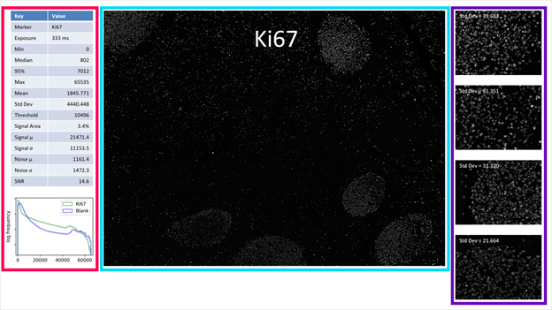 The main image in the center is the region image scaled for best fit and viewing on 4K displays (i.e. scaled to 288 ppi). This image is not in its original resolution and should not be used for detailed analysis.
(Magenta) Image information. (Cyan) Region image. (Purple) Cropped images.
On the right, there are four cropped images displayed in the original, full resolution. Within the whole region, 13 different areas are cropped at full resolution and compared for their intensity standard deviation. The four areas with the highest standard deviations, which often correspond to most contrast and information, are displayed in order.
- Open the report and evaluate the channels based on the SNR, intensity patterns etc.
4

-
Compare these images to validation staining patterns for the same antibody in the same tissue type. The patterns should follow correct cell type localization for the target marker. Failure is indicated by a FALSE designation in the channelnames_report.csv for that specific antibody.
- Open the generated channelnames_report.csv file and add TRUE/FALSE tags to each channel separated with a coma (if using text editors) or to the consecutive column if using “Excel/LibreOffice”.
Terms defined in this document
| Term | Definition |
|---|---|
| Intensity | Detector Counts |
| Signal | Intensity produced by fluorescence, both endogenous and introduced |
| Noise | Intensity not produced by light but electronic fluctuations or electronic background. |
| Stitching | Image stitching is the process of combining multiple images (tiles) with overlapping fields of view to produce a single, large image. |
| Alignment/Registration | Image registration is the process of transforming different images into one coordinate system. Registration of all channels in each cycle is performed. |
| Deconvolution | Deconvolution refers to reversing the optical distortion that takes place in an optical microscope to sharpen images/ improve definition. Practically, deconvolution can also sharpen images that suffer from fast motion or jiggles during capturing. |
| Channels | Name of the fluorescence excitation wavelengths used. May be expressed as a fluorophore name (e.g. DAPI, GFP, DsRED, Cy5), wavelength (e.g. 488, 540, 750), or color (e.g. green, red, blue). |
| Cycles | A process of adding a round of antibodies, imaging the bound antibodies, stripping the antibodies, and washing away the released antibody. |
| Regions | User defined imaging area. |
| Autofluorescence/Background | Endogenous fluorescence signal. |
| Fluorescence | Light produced by a fluorophore that is bound to an antibody tag. |
| Z-stack | A series of images produced at different stage heights or z positions. |
| X plane | Plane that determines width |
| Y plane | Plane that determines height |
| Z plane | Plane that determines depth |
| Pitch | Distance between pixels |
| Tile | Rectangular field-of-view (Figure 1). |
| Pixel | How close two objects can be and still be differentiated within an image. This is generally dependent upon the diffraction limit of light and the microscope objective. |
| Field of View | Angle through which light can reach the detector. Available imaging area without stage movement. |
| Background Subtraction | Subtraction of autofluorescence intensity from total intensity. |
For Additional Help
Please contact: Clive Wasserfall & Elizabeth McDonough.

